
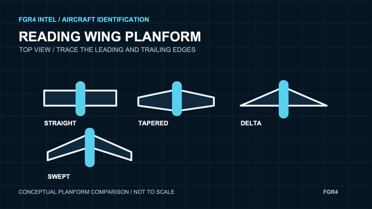
A wing planform is the shape of a wing as seen from directly above.
For aircraft identification, the planform is one of the strongest clues available. It shows how the leading and trailing edges run from the wing root to the tip, how broad or slender the wing appears and where the wing meets the fuselage.
What does planform mean?
NASA Glenn defines planform as the shape of the wing when viewed from above. The outline is bounded by the leading edge, trailing edge and wing tips. It is different from the airfoil, which is the wing’s cross-section.
This distinction matters when reading photographs and drawings. A top view reveals the wing planform; a side view is better for thickness, tail height and the position of the wing on the fuselage. The guide to aircraft side, top and front views explains what each angle can and cannot show.
Four planform clues to check
1. Sweep
Start with the leading edge. Does it run almost square to the fuselage, angle backwards or change direction along the span? A swept wing places the tips farther aft than the root, while a forward-swept wing does the opposite.
2. Taper
Compare the chord near the root with the chord near the tip. A tapered wing becomes narrower outboard. A nearly rectangular wing keeps a more consistent chord. A delta planform broadens strongly at the root and narrows towards a pointed or clipped tip.
3. Aspect ratio
NASA describes aspect ratio as a measure of how long and slender a wing is from tip to tip. For recognition, use it as a visual comparison rather than trying to calculate it from an angled photograph: is the wing long and narrow, or short and broad?
4. The wing-to-fuselage junction
Look at where the leading and trailing edges meet the fuselage. Large root extensions, wing gloves, blended shoulders or a sharply defined junction can separate aircraft whose outer wings look similar. The F-14 and Tornado comparison shows why the centre-body shape matters as much as wing sweep.
Use the whole outline, not one feature
Planform is useful because several clues appear at once, but one clue rarely identifies an aircraft by itself. Two aircraft can both have swept wings and twin tails while differing in engine spacing, nose shape, wing-root geometry and tail arrangement.
The F-22 and F-35B silhouette guide uses this combined approach. Read the wing shape together with the number of engines, exhaust layout, tail spacing and the proportions of the fuselage.
How to read a planform from a photograph
- Confirm that the view is close enough to overhead to make the outline useful.
- Trace the leading edge from root to tip.
- Trace the trailing edge and note where taper begins.
- Compare span with the apparent root chord.
- Check the wing-to-fuselage junction, tail planform and engine layout.
- Test the result against a second view or a dated reference.
Bank angle and perspective can shorten one wing or hide an edge. Do not measure a photograph as though it were a scaled drawing. When dimensions matter, use the guide to reading a three-view aircraft drawing and check the stated scale and dimensions.
Planform on a technical drawing
On a general-arrangement or three-view drawing, the plan view is normally the clearest place to compare sweep, taper, span and chord. Check the drawing’s aircraft version, date and units before using the outline as variant evidence.
The general-arrangement drawing guide gives a five-part source check. The guide to aircraft drawing dimensions explains why printed values take priority over measuring a resized screen image.
The short answer
A wing planform is the wing’s top-view shape. For identification, check sweep, taper, aspect ratio and the wing-to-fuselage junction, then combine those clues with the engines, fuselage and tail.
Explore aircraft-led planform detail
For current FGR4 work that makes aircraft geometry a central part of the composition, explore the FGR4 Vector Series.
Sources
- NASA Glenn Research Center: Wing Geometry
- Federal Aviation Administration: Glider Flying Handbook, Chapter 3
Sources checked 8 November 2026. The diagrams are conceptual identification aids and are not engineering or maintenance data.