
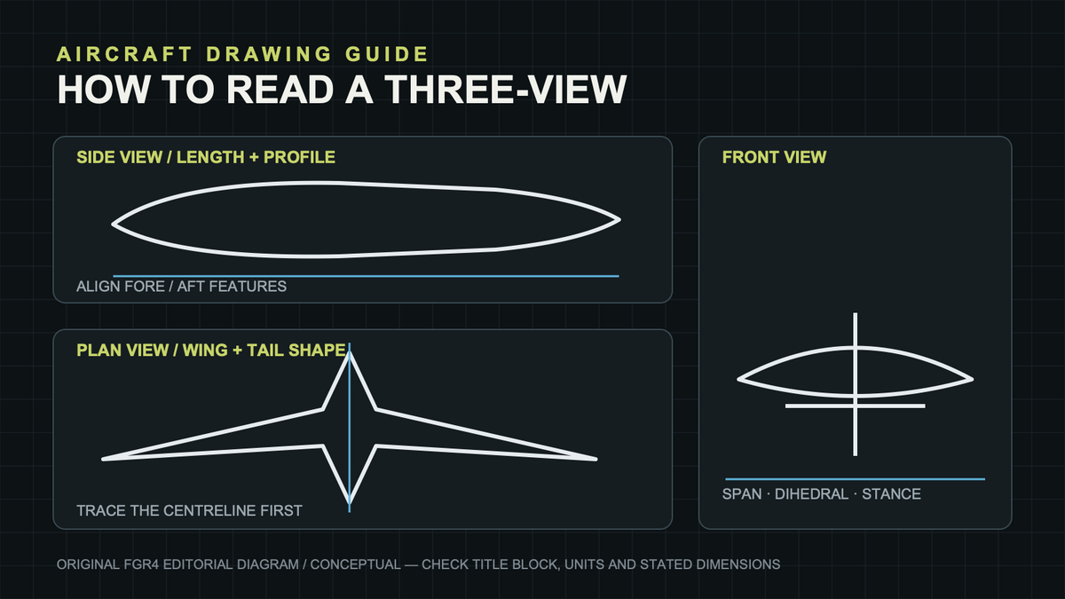
A three-view aircraft drawing shows the same aircraft from three straight-on directions: usually the side, the top and the front.
The views work together. The side view explains length and vertical profile, the plan view reveals the wing and tail planform, and the front view shows span, dihedral and the aircraft’s cross-sectional stance. Read them as one coordinated description rather than three separate pictures.
Start with the title block and stated dimensions. A displayed image may have been resized, so the drawing’s numbers outrank a ruler placed on the screen.
What is a three-view aircraft drawing?
A three-view drawing is a compact form of orthographic projection. Each view looks squarely at the aircraft, reducing perspective distortion so shape and alignment can be compared. The FAA notes that one-, two- and three-view drawings are common because a full six-view projection is seldom needed to describe an object clearly.
This makes a three-view different from a dramatic three-quarter illustration. Perspective artwork shows how an aircraft appears to the eye; an orthographic view is organised to explain geometry.
Start with the title block and scale
Before following an outline, find the drawing title, aircraft designation, revision, units and scale. Confirm that all three views describe the same configuration. A folded wing, extended undercarriage or alternate sensor fit can change the silhouette without changing the basic aircraft type.
The FAA also warns that copied or digitally resized drawings may no longer reproduce at their original scale. Use stated dimensions for accurate information. NASA’s OpenVSP guidance makes the same practical point: when an image and a stated value disagree, use the stated value.
Read the side view for length and vertical profile
The side view is the quickest place to understand nose shape, canopy position, fuselage depth, fin height and the fore-and-aft relationship between the wing and tail. It also makes vertical references easier to follow.
If the drawing uses fuselage stations and waterlines, the companion guide to FS, BL and WL aircraft reference lines explains how those coordinates locate features along and above the aircraft datum.
Read the plan view for wing and tail planform
The plan view looks down on the aircraft. It reveals sweep angle, taper, leading-edge shape, wing-root position and the relationship between the main wing and horizontal tail. It is often the most useful view for distinguishing aircraft whose side profiles look similar.
Trace the centreline first, then compare matching points on the left and right sides. Symmetry can help reveal whether a mark belongs to the design or is simply a scanning or reproduction error.
Read the front view for span, dihedral and stance
The front view shows how far the wings extend from the centreline and whether they rise or fall towards the tips. It can reveal dihedral or anhedral, engine spacing, intake position, undercarriage track and the relative height of the fuselage.
Do not treat the front view as a head-on photograph. Orthographic views remove perspective, so near and far components do not change apparent size in the way they would through a camera lens.
Align features across the three views
Choose one feature—the wing leading edge at the root, the cockpit, an engine centreline or the fin—and find it in every view. Its fore-and-aft position should agree between the side and plan views; its height or lateral position should agree with the front view.
This cross-check is the core reading skill. The introduction to aircraft general-arrangement drawings provides the wider context, while the guide to line weight in technical aviation artwork explains how outlines, hidden detail and annotation can be separated visually.
Five mistakes to avoid
- Measuring the screen without checking scale. The image may have been resized.
- Comparing different configurations. Stores, landing gear and movable surfaces can change the outline.
- Reading one view in isolation. A feature that is unclear from the side may be obvious from above.
- Assuming every line is an external edge. Centre lines, hidden detail and reference planes have different jobs.
- Treating decorative artwork as maintenance data. Operational work requires the controlled drawing and revision for that aircraft.
From technical drawing to display artwork
Display artwork can borrow the discipline of a three-view drawing without pretending to be an engineering document. The choice is how much information to retain: pure outline, selected dimensions, reference labels or a more atmospheric aircraft-led composition.
The comparison of technical labels and aircraft-led art helps set that balance. For current display work built around precise aircraft geometry, explore the FGR4 Vector Series.
The short answer
Use the side view for length and vertical profile, the plan view for wing and tail shape, and the front view for span and dihedral. Check features across all three views, then trust the title block and stated dimensions ahead of the displayed image size.
Sources
- Federal Aviation Administration: Aviation Maintenance Technician Handbook—General
- NASA: OpenVSP Modeling Introduction
Sources checked 1 November 2026. The hero is an original FGR4 conceptual diagram and is not approved maintenance data.