
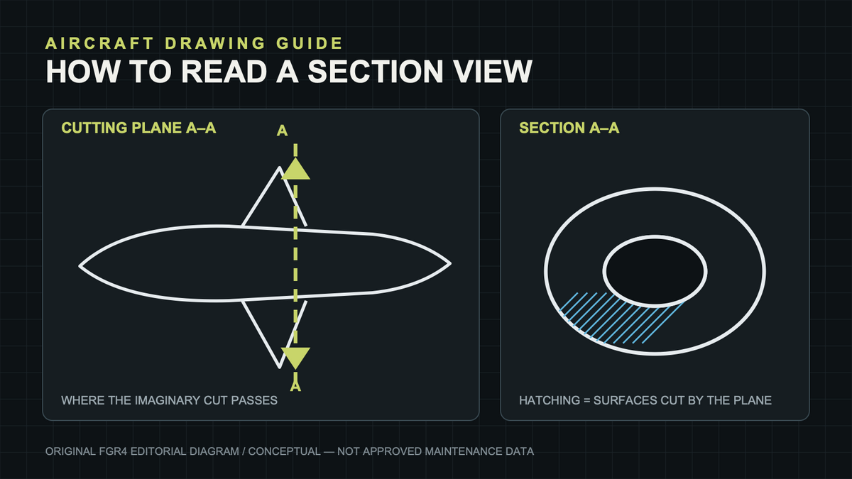
A section view shows what is inside an aircraft part or assembly by imagining that a cutting plane has passed through it.
The drawing keeps the useful geometry at the cut and removes the material that would hide it. Cutting-plane lines show where the cut is made, arrows show the viewing direction, and section lines—or hatching—mark the surfaces crossed by the plane.
Find the section label first, then match it to the labelled view before interpreting the interior detail.
What does a section view show?
An exterior view can leave internal structure buried under hidden lines. A section view replaces that clutter with an imagined cut through the object. The FAA describes a sectional view as cutting away part of an object to show the shape and construction at the cutting plane; NASA’s drawing standard says the section location is identified by a cutting plane with reference letters and arrowheads.
The result is not a photograph of a physically sawn component. It is a drawing convention that makes internal relationships easier to read, dimension and compare.
Step 1: find the cutting-plane line
Look on the parent view for a bold or distinctive line crossing the aircraft, part or assembly. Its ends normally carry arrows and matching letters such as A–A. The line tells you where the imaginary slice passes through the object.
A straight cutting plane produces a simple slice. An offset cutting plane can change direction to pass through several important features. When it does, follow every change in the line before assuming that the section represents one physical flat plane.
Step 2: follow the viewing arrows
The arrowheads show which way the drafter wants you to look after the material in front of the plane is removed. This determines whether a feature appears on the left or right of the resulting section.
Then find the view carrying the same label—usually “SECTION A–A”. NASA’s standard places sectional views close to the portion of the drawing they clarify where practical, but the label remains the reliable link when the layout is crowded.
Step 3: read the hatching
Thin, regularly spaced diagonal lines identify the surfaces that the cutting plane passes through. These are section lines or cross-hatching. Open areas are not automatically empty space: compare outlines, centre lines, notes and adjacent views before deciding whether you are looking at a cavity, a passage or a component beyond the cut.
In an assembly, the direction or spacing of hatching may change between adjacent parts so their boundaries remain clear. Some standards also use patterns to indicate materials. Do not infer a material from a pattern unless the drawing’s legend or governing standard confirms it.
Full, half and local sections
- Full section: the cutting plane passes completely through the object, revealing the whole internal profile at that location.
- Half section: one half is sectioned while the other remains an exterior view, useful for broadly symmetrical objects.
- Broken-out or local section: only a limited area is opened to reveal nearby detail without sectioning the whole view.
- Removed section: the cross-section is drawn away from the parent view and identified by its matching label.
The name tells you how much of the object is being exposed and where the resulting section has been placed. The cutting-plane line and label still control how it should be read.
How a section complements a three-view drawing
A side, plan and front view explain the aircraft’s external geometry. A section adds depth by showing what happens through a selected station. Read the three-view aircraft drawing guide first when you need the overall orientation, then use the section to inspect internal shape at a specific cut.
If the cut is located by aircraft coordinates, the guide to FS, BL and WL reference lines explains how fuselage station, buttock line and waterline references position features. The wider general-arrangement drawing guide shows how the views fit into the complete drawing set.
A practical reading sequence
- Check the drawing title, revision, units and configuration.
- Find the cutting-plane line on the parent view.
- Match its reference letters to the section label.
- Follow the arrows to establish the viewing direction.
- Identify the hatched cut surfaces.
- Separate those surfaces from outlines, centre lines and detail beyond the plane.
- Cross-check the result against another view and any written dimensions.
Line hierarchy makes this easier. The guide to line weight in technical aviation artwork explains why object outlines, annotations and construction information should not compete at the same visual strength.
Common mistakes
- Reading the arrows as airflow or movement. On a cutting plane, they establish viewing direction.
- Treating every visible line as part of the cut. Hatching marks cut surfaces; other lines can describe features beyond the plane.
- Ignoring an offset in the cutting plane. The section may combine several aligned features for clarity.
- Assuming a hatch pattern proves the material. Confirm it from the drawing legend or applicable standard.
- Using editorial artwork as maintenance data. Aircraft work requires the current controlled drawing and revision for the exact configuration.
From section drawing to display artwork
A sectional motif can add technical depth to display art, but clarity still comes first. A small number of deliberate labels and a strong outline usually communicate better than copying every engineering annotation. The comparison of technical labels and aircraft-led art helps choose the right balance.
For current display work built around precise aircraft geometry, explore the FGR4 Vector Series.
The short answer
A section view is an imagined slice through an object. Find where the cutting plane crosses the parent view, follow the arrows to establish your viewing direction, then read the hatching as the surfaces actually cut by the plane. Use the label and the other orthographic views to confirm the result.
Sources
- Federal Aviation Administration: Airframe and Powerplant Mechanics General Handbook, sectional views
- NASA: Engineering Drawing Practices—Aerospace and Ground Support Equipment
- NASA Goddard Space Flight Center: Engineering Drawing Standards Manual
Sources checked 2 November 2026. The hero is an original FGR4 conceptual diagram and is not approved maintenance data.