
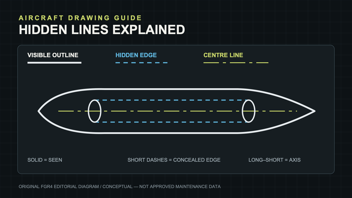
Hidden lines show edges or boundaries that exist on an aircraft part but cannot be seen from the chosen viewing direction.
They are normally drawn as short, evenly spaced dashes. Their job is to reveal concealed geometry without pretending that the hidden feature is part of the visible outline.
Start with the line pattern, then confirm the feature in another view before deciding what the hidden shape represents.
What is a hidden line?
The FAA’s Aviation Maintenance Technician Handbook explains that aircraft drawings use different standardised line types because one repeated line would turn the drawing into an unreadable collection of marks. Hidden lines identify edges that are concealed behind the object’s visible surface from that particular viewpoint.
Imagine a circular duct passing through a rectangular component. From the end, the opening is visible and can be drawn with a solid circle. From the side, the duct’s upper and lower boundaries sit behind the outer face, so they may appear as two parallel dashed lines.
How to recognise a hidden line
Look for a sequence of short dashes with regular gaps. The exact thickness and spacing can vary with the drawing standard and reproduction size, but the FAA describes hidden lines as short, evenly spaced dashes.
Follow the full dashed path. A hidden line may stop where the concealed feature meets a visible opening, changes direction or is clarified by a different view. Do not join separate dashed fragments simply because they look aligned.
Hidden line or centre line?
A centre line does a different job. It marks the centre or axis of an object and normally alternates long and short dashes. A hidden line represents a real concealed edge; a centre line represents a reference through the middle.
This distinction matters around circular features. A hidden pair of short-dashed lines can describe the unseen sides of a bore, while a long-short centre line runs along its axis. The article on line weight in technical aviation artwork explains how thickness and pattern work together to separate these jobs.
Hidden line or cutting-plane line?
Cutting-plane lines locate an imagined slice used to create a section view. They are typically stronger and carry arrows and reference letters such as A–A. Hidden lines do not carry those viewing arrows or section labels.
If a drawing feels crowded with concealed detail, a section may replace many hidden lines with a clearer view of the interior. The companion guide to section views on aircraft drawings explains how to read the cutting plane, viewing direction and hatching.
Use the other views to confirm the feature
One orthographic view rarely tells the complete story. A dashed line in the side view may become a solid visible edge in the plan or front view. Match its position across the drawing before deciding whether it is a passage, recess, internal wall or another concealed feature.
The three-view aircraft drawing guide shows how side, plan and front views align. For the wider drawing context, the general-arrangement drawing guide explains why titles, revisions, scale and configuration still come first.
Why some drawings omit hidden lines
More lines do not always make a drawing clearer. A drafter may omit concealed detail when another view or section already shows it, or when adding the hidden lines would obscure the information the view is meant to communicate.
NASA’s engineering drawing practices set formal conventions for aerospace and ground-support drawings using the ASME Y14 series. The practical reading lesson is to follow the drawing’s chosen convention and view set rather than assuming every concealed edge must appear everywhere.
A practical reading sequence
- Check the title block, revision, units and configuration.
- Identify the visible outline drawn with continuous solid lines.
- Find short, evenly spaced dashed lines within or behind that outline.
- Separate them from long-short centre lines and labelled cutting planes.
- Trace where each hidden line begins, ends or changes direction.
- Confirm the concealed feature in another orthographic or section view.
- Use written dimensions and notes ahead of measurements taken from a resized screen image.
Common mistakes
- Reading every dashed line as a hidden edge. Centre, phantom and cutting-plane lines use other dash patterns and meanings.
- Assuming a hidden feature is a hole. It could be a recess, internal wall, flange or another concealed boundary.
- Ignoring the viewing direction. An edge hidden from one side may be visible from another.
- Forcing dashed fragments into one feature. Confirm their alignment across the complete view set.
- Using editorial artwork as maintenance data. Operational work requires the current controlled drawing for the exact aircraft and configuration.
What hidden lines add to display artwork
In technical-style display art, a few dashed construction marks can suggest depth and engineering discipline. They should remain subordinate to the aircraft outline and must not imply that decorative artwork is a controlled engineering drawing.
The comparison of technical labels and aircraft-led art helps decide how much drawing language belongs in a finished display piece. For current artwork built around precise aircraft geometry, explore the FGR4 Vector Series.
The short answer
Short, evenly spaced dashes normally identify a concealed edge. Long-short dashes mark a centre or axis, while a solid line shows a visible boundary. Confirm any hidden feature in another view or section before interpreting its shape.
Sources
- Federal Aviation Administration: Aviation Maintenance Technician Handbook—General, aircraft drawing lines
- NASA: Engineering Drawing Practices—Aerospace and Ground Support Equipment
Sources checked 3 November 2026. The hero is an original FGR4 conceptual diagram and is not approved maintenance data.