
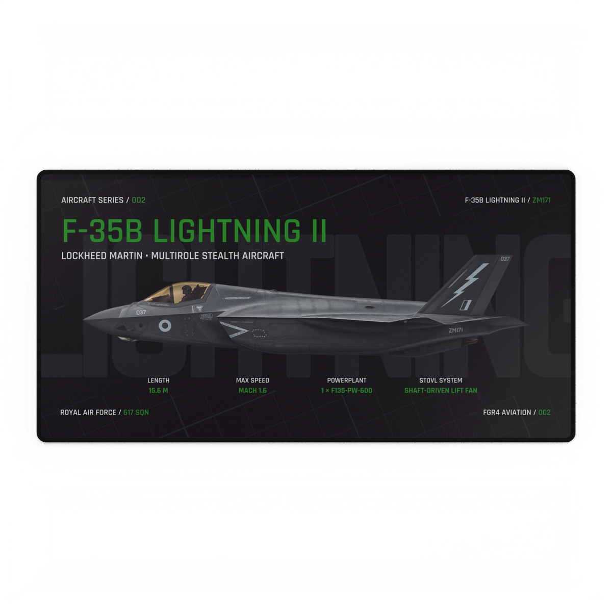
The F-35B uses a shaft-driven lift fan because its short take-off and vertical landing role needs vertical thrust at the front of the aircraft as well as at the rear. The fan sits behind the cockpit and works with a swivelling rear exhaust nozzle and small roll-control outlets in the wings. Together, those parts turn power from the main engine into a balanced vertical-lift system.
The live Aircraft Series design shows the F-35B in side profile, the clearest angle for locating the lift fan between the cockpit and main engine.
The lift fan is not a second engine
The most useful distinction is mechanical. The lift fan does not carry its own separate engine. Rolls-Royce says the aircraft’s main engine sends up to 29,000 shaft horsepower through a driveshaft and clutch to the fan. The fan then produces cold vertical thrust near the front of the aircraft.
In conventional flight the F-35B behaves as a jet powered by its rear engine. When the aircraft converts for short take-off or vertical landing, the clutch engages the lift-fan drive and doors above and below the fan open. Power that began in the main engine now turns the counter-rotating fan behind the cockpit.
Four parts make the F-35B LiftSystem work
“Lift fan” is often used as shorthand, but the complete Rolls-Royce LiftSystem has four linked elements. Reading them as one system explains why the aircraft needs more than a downward-facing nozzle:
- LiftFan: creates the forward vertical-lift force.
- Driveshaft and clutch: transfer power from the main engine to the fan when STOVL mode is selected.
- Three-bearing swivel module: turns the main engine’s rear thrust downwards to create the rear vertical-lift force.
- Roll posts: direct bypass air through outlets in the wings to control roll during low-speed and hovering flight.
FOLLOW THE POWER AND THRUST · SIMPLIFIED, NOT TO SCALE
Produces propulsion and supplies mechanical power to the lift-fan drive.
The clutch and driveshaft turn the fan, creating forward vertical lift.
The rear exhaust turns downwards to create rear vertical lift.
Wing outlets provide the lateral control needed to hold attitude.
Why put the fan behind the cockpit?
A single downward-turned exhaust at the tail would place the main vertical force too far aft to support the whole aircraft by itself. The lift fan provides another strong vertical force ahead of the aircraft’s centre, while the swivel nozzle acts at the rear. The system can then support and control the aircraft around its centre rather than trying to hang it from one point at the tail.
This fore-and-aft arrangement is the reason the fan’s position matters. It occupies the fuselage volume immediately behind the cockpit because it must act as the forward part of the vertical-lift system. The wing roll posts complete the control picture by helping manage left-right attitude.
What problem does a shaft-driven fan solve?
Lockheed Martin describes the shaft-driven approach as a way to address the temperature, velocity and power challenges associated with direct-lift systems. The forward lift comes from a large fan moving air, while the rear of the aircraft uses vectored engine exhaust. It is a combined arrangement rather than several small jet engines distributed through the fuselage.
That matters when reading the aircraft’s shape. The broad upper door behind the cockpit is the lift-fan inlet, not an air brake. Smaller doors and openings around the upper fuselage and wings belong to the wider STOVL installation. When those doors are closed in normal flight, the machinery is much less obvious than the F-35B’s external silhouette suggests.
Short take-off and vertical landing are different jobs
STOVL joins two related capabilities. During a short take-off, forward speed lets the wings contribute lift while the propulsion system vectors part of its thrust downwards. During a vertical landing, the LiftSystem supports the aircraft without a conventional runway roll. The F-35B’s defining feature is therefore the complete conversion between forward flight and powered lift, rather than the fan in isolation.
The lift system is what gives the B variant its distinctive short take-off and vertical landing option, but that design fact should not be stretched into unrelated claims about mission performance or current fleet availability.
How to recognise the F-35B system in a photograph
Start with a side or three-quarter view and look immediately behind the cockpit. In STOVL mode, the large upper lift-fan door rises from that section of the fuselage. Then check the rear nozzle: it should be turned down rather than pointing straight aft. Finally, look for the smaller open doors and outlets that accompany the conversion.
Aircraft markings alone cannot prove the variant, so use several structural clues. The F-22 versus F-35B silhouette guide provides a broader identification method, while the older RAF and Royal Navy F-35B variant explainer adds UK service context. For a different example of reading aircraft design from visible structure, follow the forebody edge in the SR-71 chine guide.
Choose the view by the question
A technical side profile makes the cockpit, fan location and engine arrangement easiest to place. Browse the Aircraft Series for that structured presentation. A three-quarter composition shows more of the F-35B’s angular planform and upper fuselage; the live F-35B Lightning II Vector Desk Mat uses that approach.
The short answer
The F-35B uses a lift fan to create forward vertical lift from power supplied by its main engine. A swivelling rear nozzle supplies the rear vertical force, and wing roll posts help control the aircraft. That four-part system gives the B variant its short take-off and vertical landing capability. The fan is the most visible component, but the complete LiftSystem is the real answer.
Sources
Sources, live products and related articles checked 20 October 2026. The four-part system card is an illustrative reading aid and is not a scale engineering drawing. FGR4 Aviation is not presented as affiliated with or endorsed by Rolls-Royce, Lockheed Martin or any operator.